Ian K said...
From what I can gather the switch mode regulators work by tapping current into one end of an inductor at high frequency by switching the supply. Then I suppose the tapping frequency is regulated to make sure the load at the other end of the inductor has the specified voltage across it? Anybody found a simplified circuit diagram of one? Must be a diode or two involved - they still use diodes don't they?
Ian, a switchmode power supply simply chops up DC into AC and uses a transformer for the conversion. The transformed AC is then rectified back into DC.
A
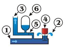
buck converter, on the other hand, uses just an inductor which is charged at a certain duty cycle:
upload.wikimedia.org/wikipedia/commons/5/52/Buck_operating.svg It can only step down, and is very efficient, especially compared to the linear (LM78xx-series) regulators. In order to provide accurate output voltage, there is a feedback loop (not shown in the above picture) which regulates the frequency and duty cycle of the supply side. A very typical regulator IC would be the LM2576, which requires just the inductor, diode and a few external capacitors, and has a typical conversion efficiency of over 80% (there are even more efficient versions). Despite it not being linear, the output voltage is quite clean, and with minimum ripple.
A car inverter is a switchmode supply. It takes the input 12V, chops it into high-frequency (as in, higher than 50 Hz) AC, pushes it through a transformer, and integrates (smoothes) the output. The chopping circuit is modulated appropriately, in order to provide an approximation of a 50 Hz sine-wave after the integration step. There is a "flyback" control loop to provide accuracy. The additional step up in voltage, as well as the DC offset removal, are done by a secondary transformer, operating at 50 Hz.