jaumet forum posts in last 60 days

jaumet
jaumet
WA
6 posts
WA, 6 posts
20 Aug 2026 12:47am
sailortrash said..

jaumet said..


utcminusfour said..
Welcome, Jaumet!
I am keen to learn and discuss, but I am not an expert on airfoil theory. I have picked up a little through school, work, and my own interest in foils, but this discussion may be slightly beyond my depth, so a couple of questions first.
Could you clarify how you define camber and reflex, and what distinguishes one from the other? I have heard reflex described as a convex hook (down) in the aft portion of the lower surface. In that description, it is related to the camber line but treated as a separate feature. You seem to be describing reflex as the aft portion of the section turning upward, or effectively moving the trailing edge up. Some clarifications of the nomenclature would help me a ton.
We also need to get you the ability to post pictures. I would really like to see two comparable sections, one with the stronger nose-down pitching moment and one with the subtle reflex that reduces it. I think seeing the difference would make this click for me. Maybe PM me the images and I can post them?
I think I found the Takeoff Technologies home page, but not the article you mentioned. Regardless, it looks like an amazing resource that was not on my radar. Thanks for posting!


Thanks utcminusfour,

I am planning on doing more posts like this here,
Its nice to engage with the community, so hopefully I can get the ability to upload soon.
Meanwhile you can find the article with images here:
app.takeoff-technologies.com/community/blog
It makes it easier to follow

best,
Jaume


Wouldn’t an “auto” adjusting stabilizer be a good for the kind of foils we use (one mast, one wing, one stab)? On the water, i get the sense that a given AoA of the stab works well within a certain speed range, but ideally AoA would change with speed.


looks like you could support this open source project


jaumet said..


utcminusfour said..
Welcome, Jaumet!
I am keen to learn and discuss, but I am not an expert on airfoil theory. I have picked up a little through school, work, and my own interest in foils, but this discussion may be slightly beyond my depth, so a couple of questions first.
Could you clarify how you define camber and reflex, and what distinguishes one from the other? I have heard reflex described as a convex hook (down) in the aft portion of the lower surface. In that description, it is related to the camber line but treated as a separate feature. You seem to be describing reflex as the aft portion of the section turning upward, or effectively moving the trailing edge up. Some clarifications of the nomenclature would help me a ton.
We also need to get you the ability to post pictures. I would really like to see two comparable sections, one with the stronger nose-down pitching moment and one with the subtle reflex that reduces it. I think seeing the difference would make this click for me. Maybe PM me the images and I can post them?
I think I found the Takeoff Technologies home page, but not the article you mentioned. Regardless, it looks like an amazing resource that was not on my radar. Thanks for posting!


Thanks utcminusfour,

I am planning on doing more posts like this here,
Its nice to engage with the community, so hopefully I can get the ability to upload soon.
Meanwhile you can find the article with images here:
app.takeoff-technologies.com/community/blog
It makes it easier to follow

best,
Jaume


Looks like u could support this open source project!

3hxyqkzsskexg9sja54q3l.streamlit.app/


Yes of course!
This is what aircraft do! They change the AoA of their Horizontal Tails depending on the speed and CG (fuel is burned over time).
Its just hard to manufacture at these small scales.

Your project, looks very nice!
Unfortunately, I am quite busy devloping our Conceptual Design Tool.
You can check it out in: app.takeoff-technologies.com
You can also use many of the features for free!

best,
Jaume

jaumet
jaumet
WA
6 posts
WA, 6 posts
20 Aug 2026 12:43am
mr love said..
This video from Greg at Omen foils has the best explanation of our foil geometry and the forces involved that I have found, well worth a watch.....It shows the difference between our geometry and an airplanes , this is what I was poorly describing when talking about a lever.


Jaumet.......Could you comment on these 2 scenarios....

Firstly as you can see in Gregs video it is both drag and front wing -Cm that contribute to downward pitching in our foil systems.

Scenario 1...........High camber ( moderate rear camber) front foil.......High lift profile .....lets say a Cm of -.1 at 1 degree AOA
Scenario 2....... Moderate camber reflexed profile......Low/ Medium lift profile.......Cm -.05 at 1 degree AOA

Due to the lower lift of the reflexed foil we assume we need to increase the foil area to match higher cambered foils lift for the same rider, same conditions etc...lets assume 12% larger.... The larger front wing has a lower -Cm but due to being larger more parasitic drag from the increased surface area.
With both drag and negative Cm causing our board to pitch down which scenorio will pitch down worse at high speed?
And sorry in advance as I know there is so much math involved you won't want to answer this and I don't expect you to. I am just interested in your thoughts.... 😎 And no I have not done the math.

Thanks


Hey Mr Love,


Greg's video is super nice, he is so good at explaining complex things easily!
As with eveything in design, everything affects everything and so this can only be properly solved with an optimization loop.
Nevertheless, from my experience I dont think the reflex penalizes the Max Lift so much in a well designed profile.
You can still design a section that has both high camber and reflex.
Nevertheless to maintain a given amount of trim/stability, if the Wing area increases, you also need to compensate in the tail volume somehow.

jaumet
jaumet
WA
6 posts
WA, 6 posts
19 Aug 2026 5:17pm
thedoor said..
If we keep asking Jaumet questions maybe he will hit image posting status😂

Hi Jaumet

From your article


What I am hearing is that for pitch stability the further the COG is from the Neutral Point the more likely the craft will continue on its pitch. From practical experience I totally get that. Longer heavier boards and longer fuselages seemed to be easier to gybe because if you messed up your inputs it would tend to carry on its flight path . However, when navigating swells or jumping shorter boards and shorter fuselages were necessary to unlock the pitch control.

So if I have that correct, then if the goal was to improve stability we could ride with more board out in front. How do we estimate the Neutral Point of the system (foil, board and rider)?

I guess I am wondering how we could manipulate moving the neutral point aft by changing gear or geometry.

One more question: I am assuming that as you move the COG forward, you need to generate more lift with the foil to get the craft to fly?

Hey thedoor!

Yeah you got it right.
If you want to improve pitch stability on an wing-tail configuration you can either move the CG forwards or moving the NP Aft.
In these foiling craft the position of the CG is driven mainly by the weight of the Rider. However, the position of the rider cannot be arbitrarily set like in an aircraft (a wingfoil has no control surfaces) and so its position is a consequence of the overall external pitching moments (Drag and Lift of the Foil, Board and Sail). Lets say that the rider position is the control surface for pitch balance.

Therefore the only thing that we can actively in this case to improve Stability to move the NP aft is to increase the Tail Volume (again aircraft terminology).
In plain english this is to produce as much lift and as far aft as possible. This can be done by means of a larger fuselage (longer lever) or by making the stab larger or running it at a higher angle of attack.

Making the board longer from the front would not impact the stability as it does not affect the weight or the forces on the system much.

Hope this answers your question
jaumet
jaumet
WA
6 posts
WA, 6 posts
15 Aug 2026 5:31pm
mr love said..
Reflex is as Jaumet describes, a turn up on the trailing edge of the upper, low pressure side of the wing. Commonly seen on flying wings to improve pitch stability.... The concave / turn down on the underside ( high pressure) trailing edge is often described as " rear loading" and increases lift and an excellent way to lower the stall speed of a foil. But it does increase the negative pitch moment as Jaunet explains.
Reflex does decrease lift....so to have a less negative pitching moment you may be having to increase your foil area which adds drag. Bear in mind that on our foil configurations where we a standing well above the lifting wing on top of a lever an increase in drag at the bottom of that lever will make the board want to pitch down, it literally is a balancing act.
Jaumet, I would appreciate your opinion on rear loaded profiles for foiling....the pros and cons...


Hey Mr Love,


Loading the aft portion of the profile is known as aft-camber or hook.
It is a common trick in profile design that has many consequences, and as you say, with everything that is design or operation or foils,
its a balancing act.

Increasing the hook of the section increases its Maximum Cl as you are deflecting more flow directly downwards. Its not the only way to increase Max Cl, but its a good one as it does not decrease the cavitation speed like if you were messing with the LE radius. Additionally, it often increases the lift slope of the section, making it ideal for pumping.
The drawback is that the Cm of the profile gets very negative as the Centre of Pressure (CoP) moves very far aft (hence this whole thread).
Additionally, these sections may be physically brittle as the absolute thickness of the profile near the trailing edge may become quite thin.
When designing sections with a lot of hook one must be cautios not to be too eager with potential gains, as overdoing it may lead to flow separation, both in the upper and the lower surfaces.
One can design a very pretty profile with a nice hook that is super optimized for some Cl. However one must be aware that aerodynamics are very non-linear and that this hook strategy does not work in all flow regimes, and so it must be tested in the tools to see if the expected operating conditions favour a some amount of rear-camber or not.

I hope this clarifies your question,
Jaume



jaumet
jaumet
WA
6 posts
WA, 6 posts
15 Aug 2026 5:08pm
utcminusfour said..
Welcome, Jaumet!
I am keen to learn and discuss, but I am not an expert on airfoil theory. I have picked up a little through school, work, and my own interest in foils, but this discussion may be slightly beyond my depth, so a couple of questions first.
Could you clarify how you define camber and reflex, and what distinguishes one from the other? I have heard reflex described as a convex hook (down) in the aft portion of the lower surface. In that description, it is related to the camber line but treated as a separate feature. You seem to be describing reflex as the aft portion of the section turning upward, or effectively moving the trailing edge up. Some clarifications of the nomenclature would help me a ton.
We also need to get you the ability to post pictures. I would really like to see two comparable sections, one with the stronger nose-down pitching moment and one with the subtle reflex that reduces it. I think seeing the difference would make this click for me. Maybe PM me the images and I can post them?
I think I found the Takeoff Technologies home page, but not the article you mentioned. Regardless, it looks like an amazing resource that was not on my radar. Thanks for posting!


Thanks utcminusfour,

I am planning on doing more posts like this here,
Its nice to engage with the community, so hopefully I can get the ability to upload soon.
Meanwhile you can find the article with images here:
app.takeoff-technologies.com/community/blog
It makes it easier to follow

best,
Jaume

jaumet
jaumet
WA
6 posts
WA, 6 posts
12 Aug 2026 6:02pm
Hey guys - I am new around here.
I am a fellow Americas Cup and Hydrofoil designer and I thought I'd say hi with a topic we all have discussed time again.
(Unfortunately I still can't paste images here so you can find the original article in the Takeoff-Technologies Community Hub)

Decoding Reflexed Airfoils
Airfoil reflex is one of the most misunderstood topics in the hydrofoil community. The goal of this article is to clarify what reflex is and how it influences the performance and handling of a hydrofoil.
One of the simplest ways to increase a profile’s maximum lift coefficient (Cl) and tailor its performance to specific operating conditions is by adding camber. Tailoring a good camber distribution increases lift generation while reducing drag at the targeted design points. However, this inevitable also increases the section's nose-down pitching moment (its pitching moment coefficient (Cm) becomes more negative).

To fly in equilibrium, this nose-down moment must be balanced by an opposing nose-up moment which is typically generated by the rear stabilizer or, to some extent, by rider weight transfer.

What Is Pitch Stability, and Where Does Cm Fit In?
For a hydrofoil to fly comfortably, two independent conditions must be satisfied:

- Trim: The foil must be able to trim to its required operating lift coefficient, meaning the total pitching moment is zero (Cm=0) at the corresponding angle of attack.
- Static Stability: The system must be statically stable. If a wave or gust disturbs the craft, it must naturally return toward its trimmed attitude.

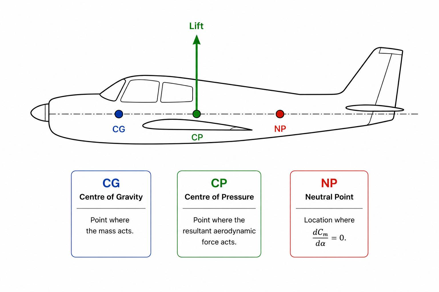
Longitudinal stability is governed by the position of the craft's Neutral Point (NP) relative to its Center of Gravity (CG). For positive static stability, the Neutral Point must lie behind the Center of Gravity. The distance between them, known as the static margin, determines how strongly the craft resists to pitch disturbances.

Mathematically, the static margin sets the slope of the pitching moment curve with respect to the angle of attack: dCm /da
- Positive Static Margin: Produces a negative pitching moment slope (dCm/da < 0). If a gust increases the angle of attack, the craft naturally generates a restoring nose-down moment, returning it to its trimmed condition. A larger static margin creates a stronger restoring tendency and a more "locked-in" feel.
- Small Static Margin: Produces a gentler restoring moment, resulting in more responsive, agile handling.

The Role of Airfoil Geometry and Cm
The Neutral Point is determined primarily by the geometry of the complete system: main wing sweep, stabilizer area, fuselage length, and their respective lift characteristics.
By contrast, the airfoil section's pitching moment coefficient (Cm) has little influence on the neutral point itself. Instead, it determines how much balancing force the stabilizer must generate to achieve trim. This is because the section pitching moment remains nearly constant over the normal operating range, changing Cm shifts the entire pitching moment curve up or down without significantly changing its slope.

How Reflexed Airfoils Can Help
A highly cambered airfoil produces a large nose-down pitching moment, requiring the rear stabilizer to generate a continuous balancing force. That balancing force incurs additional induced drag reducing overall efficiency.
By curving the trailing edge upward, a reflexed airfoil reduces the section's nose-down pitching moment, moving Cm closer to zero.

Because the baseline pitching moment changes while the pitching moment slope (dCm/da) remains essentially unchanged, the hydrofoil retains the same static stability but requires less trim effort:

- Lower Trim Drag: Reduced downforce requirement on the stabilizer lowers total system drag.
- Greater Control Authority: The stabilizer retains more control range because it isn't working as hard just to keep the craft in static equilibrium.

Summary
Reflex does not make a hydrofoil inherently more or less pitch stable. Instead, it improves the efficiency with which a stable hydrofoil can be trimmed.

Lets open the discussion!