This is interesting one to troubleshoot. I think thanks to the hero that was cutting my shore cable, I have had a few electrical issues to sort out. The last of these is the electric winch which stopped working. I have Harken 46ST as winches, with the main halyard winch as electric (lazy I know, but hauling that thing up by yourself gets old pretty quickly). It's a 2 speed, with a dual button mounted in the cockpit below the winch.
Press either button, zip squat nada, no dice. So out came the mulltimeter and into the wiring time. It turned out to be more intelligent than I thought. I was expecting two simple relays that used the cockpit buttons as control circuits for actuating the relays to allow the big fat 30amp DC power circuit to the two winch motor connections, one for the high speed and one for the low speed mode.
But nooo. Harken use a separate black box called a dual controller that houses the 30amp DC circuits and the cockpit button inputs. It acts as a safety device as well as a relay switching widget, as it provides a current overload cutoff as well as a few other simple cut off features, like pressing both buttons at once etc etc.

I tested the control circuit first. Pressing the cockpit buttons and the dual controller receives the power inputs at the correct inputs. Release the button and the power goes off. Cool. The control circuits are working.
I then tested the 30A DC circuits in and out. Power was confirmed going into the dual controller from the battery, but regardless of buttons pressed, no 30A DC power out on either of the two thick cables going to the winch motor.
Ergo, the 2 way relay in the dual controller is not switching. Problem solved! The dual controller box is not outputting DC voltage, so it needs to be repaired. I contacted Harken. Turns out they don't do repairs, you have to buy a new one. So I got a price, thinking it'd be a few hundred dollars as it is after all a simple relay device. Then I got the quotes, about $1000. Ouch.
That to me is borderline criminal for a relay with some inputs, so I'm having a go at repairing it myself. Pulling it apart, it's simply a small circuit board that sits between the relay/solenoid (dunno what you should call it) and performs the safety overrides that controls whether the relay is allowed to switch. Which is exactly the problem, something is preventing that relay from switching the 30A DC circuit to the motor.

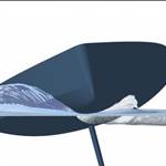
The relay tests up fine and switches merrily every time we test, so that part is all good.The focus now is on the circuit board that controls it. I can see power getting to the board, and I can see the button inputs powering when they are supposed to, but I see no corresponding voltage output to switch the relay. (the control outputs are the blue and white wires in the picture, one is for low speed and one is for high speed.)The focus at the moment is to determine if a component on the board has failed (which looks unlikely, I can't see any signs of blown components) or whether it is an input to the board that has failed. This should be simple enough as there is no other inputs to the board except power, the buttons and the current overload sensor.
It might be as simple as the current overload circuit is toast, and it's actually doing its job. That's what the big brass angle bracket running through the current sensor on the circuit board is, it's the main 30A DC input to the relay. It's not helped by the not unexpected discovery that Harken don't even publish circuit diagrams which adds to the challenge....sigh. What ever happened to proper post sales support for expensive widgets?
So I'm trying to map out this and any other internal circuit board fail safes and test them individually till I isolate the problem.
You gotta love boats!